文章描述了将经典街机游戏《Spy Hunter》移植到现代控制台的过程。主要挑战包括模拟方向盘和油门的输入信号、处理灯光面板和音频输出、以及将传统控制方式适配为现代控制器操作。项目涉及复杂的电路设计和硬件适配,最终目标是使游戏在保留原版体验的同时易于现代玩家操作。 2025-10-8 02:0:35 Author: www.zdziarski.com(查看原文) 阅读量:19 收藏
On October 7, 2025 by Jonathan Zdziarski
Spy Hunter
Spy Hunter is a well loved classic, and by far the most challenging and ambitious title I have worked on to date. While the purists will insist that the only way to enjoy the game is on the original arcade hardware, many (many!) adaptations to various consoles have been met with incredible success. My goal was to adapt the original arcade version of this to work on my coffee table with a JAMMA super-gun, or in a JAMMA multi-cabinet that wouldn’t necessarily have a dedicated steering yoke or pedals. To accomplish this, Spy Hunter comes with many new challenges over and above other games I’ve adapted:
- The MCR board uses a daughter board to obtain readings from potentiometers for both the steering wheel and accelerator. Unlike TRON’s spinner, these controls are entirely analog and are read into absolute values using an ADC (analog-to-digital converter). There is one data “bus” sharing inputs into the MCR board for both steering and accelerator, and the value being read is determined by a separate pin on the main board. Depending on what the main board calls for, you must provide the correct value to the pins.
- One of the more ingenious ways to avoid piracy, Bally/Midway used a lamp panel to display the weapons available to the player at any given time, along with a flashing lamp indicating when the weapons van could be summoned. Along with the steering controls, this binds the software to the hardware of the cabinet. Without this lamp panel, the user has no idea when they can call the weapons van, or what weapons they receive from it. A lamp driver reads the latches set by the game and illuminates the correct bulbs.
- The board has two separate audio channels, one for effects and one for music. A daughter board named the “Cheap Squeak Deluxe” plays the Peter Gunn theme. This is mixed across two separate amplifiers in the sit down version of the game. I’ll have to merge four audio channels (L and R) into a single mono channel suitable for JAMMA.
- An accelerator pedal must somehow be adapted to controller buttons.
- The gear shift is a physical stick that shifts between high and low. This, too, will need to be adapted to modern controls.
- In addition to emulating all of this, the adaptation must somehow be easy to play with a controller or joystick.
Steering and Acceleration
The biggest challenge to this project by far was instrumenting the steering and acceleration. I wanted to remove the analog potentiometers since modern controls don’t use them. I’m going to be playing this with a Nintendo Pro Controller gamepad. The Absolute Position board is a daughter board that converts these analog signals into digital values for the main board to read. I have to emulate this entire board in order to send these same digital signals without using any pots.
To do this, I started with the same foundation as I used for TRON and RoadBlasters: an NE555 timer chip that clocks a counter when you push Left or Right. But this counter is entirely different than the others. This is an 8-bit counter whose dead center is around the middle of the counter (0xC8 uncalibrated). Instead of reading the counter at the beginning of each mini-game, like TRON, the game is calibrated to report specific values that correspond to steering commands. In addition to this, I needed a return-to-center function for this game so that when you take your hands off the steering controls, you return to moving straight. Lastly, I needed a way to avoid rolling the counter over. Unlike TRON, where Tron’s arm moves a full 360 degrees, rolling the counter in Spy Hunter means that you go from steering extreme left to suddenly steering extreme right (or vice versa). That would be an unmanageable driving experience.
There are some limitations to the 74LS491 I used in TRON that made it a poor candidate for use in Spy Hunter. Firstly, the LS491 is a 10-bit counter (not 8-bit), and so it’s instrumented around bits I’m not even using. For example, I can’t load a specific value (e.g. 0xC8) directly using the parallel load function, because the pins for bits 2-7 are considered unimportant in a 10-bit counter, and that pin is shared – so I have no granularity. There’s also no easy way to know when I’ve reached the max 0xFF value used in an 8-bit counter, so that I can stop counting higher. Instead, it made more sense to build a circuit with two cascading 74LS191s. The LS191 is a 4-bit up/down counter functioning much the same as the LS491. It has a rollover pin so that I can stitch multiple counters together and cascade the overflows or underflows.

74LS191 pinout
To tie two LS191s together in a cascading architecture, the RCO (ripple clock) pin from the IC used for the lower four bits is used to drive the CLK for the next IC. Both chips share the same D/U (UP/DOWN) signal. When you clock the lower four bits, that counter continues to grow until hitting its max value, which then triggers the ripple clock. The ripple clock then tells the high counter to count up or down. Regardless of whether you’re incrementing or decrementing the counter, the lower four bits are intended to roll, and the signal will then clock the upper counter to increment or decrement. e.g. 11110000 goes to 00001000 when counting up, and 00001000 goes to 11110000 on the way down.
The LS191 has some other neat features that makes it a good candidate for Spy Hunter. The MAX/MIN pin signals when the chip reaches its minimum (if you’re counting down) or its maximum (if you’re counting up). This allows you to know when you hit a boundary, at which point I’m able to raise the CTEN pin (count-enable) which will stop counting. So if I keep holding the controller in one direction, the counters will stop counting down at 0x00 and stop counting up at 0xFF. I did this by wiring both MAX/MIN pins into a NAND and then inverting it into CTEN. So if MAX/MIN are both raised high, the first NAND will output low. Inverted, this will disable the count-enable whenever the two chips together hit a min or max (0x00 or 0xFF). It’s quite nice that MAX/MIN is smart enough to only signal when you hit the edge of the direction you’re counting in.
Lastly, the LS191’s LOAD pin allows me to parallel load any value directly into the counters. Since I know the default value for a centered steering wheel, I can hard-wire pins A, B, C, and D and then whenever neither 1P Left or 1P Right are pressed down, set the LOAD pin to a low state to immediately center the wheel. This can be done with a simple XOR.
I like the LS191 so much that I’m back-porting this design to the TRON board. Why? Because the 74LS491 is a rare chip, and costs around $8. A 74LS191, however, runs about $0.60 cents. There’s no need to use an identical chip to the original TRON game when that chip in and of itself was more or less a hack.
The same approach to counting could be done for accelerator pressure, but instead I decided to use hard-wired values for min and max acceleration depending on whether a button is pressed. This makes for a better experience than having to also manage an accelerator on a controller. Push down, you accelerate, let go and you decelerate. This allows enough room to feather the “pedal” without requiring the user also manage up/down controls for it.
Multiplexing
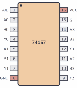
Now this all sounds fine, and I’d love to be able to simply wire up a timer to this rig and call it done. Unfortunately, it’s not that easy. As I mentioned, there is a makeshift data bus involved here, and the same pins that read the steering wheel value on the main MCR board are also used to read the accelerator value. The SEL pin (J5, pin 17)’s value (high or low) determines which of these two values it’s expecting. You can watch this dance happen with an oscilloscope. This means we have to constantly switch the output whenever SEL changes. To do this, I’ve employed a multiplexer. The 74LS157 accepts four bits of input from two different sources, and connects the selected input to a single set of outputs depending on which is selected. Because we have eight bits of output, we’ll need two of these ICs sharing the same SELECT signal.

74LS157 Pinout
The outputs of the two steering counters are connected to the pins for input A. Whenever input A is selected, the counter’s output pins are connected by (and read by) the main board. When input B is selected, I hard wired bits corresponding to either 0x00 or 0x1F (the maximum accelerator value) is what’s seen by the main board. As the SEL pin pulses, so will the SELECT pin on the multiplexers, giving the main board the correct values. So the multiplexer is constantly getting input from both inputs, but only connecting one of those outputs to the main board at a time. NOTE: I’m still playing with the correct hard-wired accelerator values and will update this after testing some prototypes.
By emulating the values processed on the Absolute Position board, I’m able to eliminate this daughter board entirely from my setup when using the adapter. The steering/acceleration counter and multiplexer circuit presently looks like this.

Steering-Acceleration-Multiplexer Circuit
L/H Shifter Latch
In order to emulate the L/H shifter, I’ve built a toggle latch. This uses a 74LS74 latch combined with a NOT gate to set the latch’s value to its inverse every time the user presses a single button. It’s a very simple circuit, really, to store and flip a single bit. This bit is read by a pin on the main board to put you in low or high gear.

Gear Shift Latch
Lamps
The indicator lights are an essential part of Spy Hunter. While I do plan on making a small, remote LED strip later on, I wanted to make sure I could display the lights correctly on the adapter first. The lamp board is a separate daughter board included in the cabinet and (as I mentioned) was an ingenious way to prevent piracy by making the game hardware-dependent.
Lamp boards are hard to come by on their own these days, and it only stands to add a lot of extra power and complexity to a setup to have to wire one up just to play the game. So in addition to emulating the Absolute Position board, I’ve made use of the CD4099B latch to emulate the Lamp Driver board as well.
The lamp board programs the latches on a CD4099B directly, and if you follow the schematic all the way back to the main board, it becomes a simple wiring problem. Once you figure out how to map the inputs and outputs, you can map the outputs to a set of low power LEDs with resistors in front of them (instead of amplifiers and 12V bulbs). To make it easier to read, I’ll be using the same colors from the game – orange LED for the weapons van, and a combination of red and purple LEDs placed specifically for individual weapons to mirror the cabinet. With this, it should be possible to play the game!
Other Improvements
I’ve learned a few things since building TRON, which I’ve incorporated into later revisions of TRON as well as into Spy Hunter. Namely, the value of pull-up and pull-down resistors on input and output pins is crucial for compatibility and chip lifetime. I had originally designed TRON using TI chips, which could handle the extra current however quickly found that cheap generic chips couldn’t. Adding resistors in front of my pins limits the inbound and outbound current. I also added a 470R resistor to the composite sync, which prevented certain cheap chips from blanking out after seeing too much current.
Lastly, my amplifier circuit has gotten a bit better, and the way I’ve set up the two distinct audio sources, you can mix them before sending both to the preamp.
Controls
Interfacing with the game is one tough challenge, but making the controls a good experience is quite another. To play this game, I’ve had to make use of the extension harness to interface with buttons 5 and 6 on a controller. This will allow me to map the controls in a comfortable configuration (Nintendo Pro Controller layout below)…
- Left and Right for steering, with return to center (and adjustable trim pot on the adapter to set the steering speed)
- B accelerates. Releasing B equates to taking your foot off the pedal.
- Shift L/H toggle is A
- Missiles and Machine Guns are the L and R buttons at the top side of the controller
- Smoke and Oil Slick are buttons Y and X.
- Weapons Van is the “+” button (equivalent of 1P Start, since Spy Hunter uses the Weapons Van button to Start).
Prototyping
I’m currently fabricating some prototypes and will be testing and tweaking these circuits over the next several weeks on a Spy Hunter stack. The only boards I expect to need are the three MCR boards and the Cheap Squeak Deluxe for music.


如有侵权请联系:admin#unsafe.sh