
好的,我现在需要帮用户总结一篇文章的内容,控制在100字以内,而且不需要特定的开头。首先,我得仔细阅读这篇文章,了解它的主要内容和结构。 文章主要讲述了消费电子设备充电标准的发展历程,从早期的USB接口到现在的USB Type-C。作者详细介绍了各个阶段的技术变化、存在的问题以及解决方案。比如,早期的BC1.2标准、USB Type-C的引入、各种快充协议的出现以及最终的标准化过程。 接下来,我需要提炼出关键点:时间跨度(过去十年)、核心目标(统一充电接口)、主要技术(USB Type-C、PD标准)、遇到的问题(碎片化、兼容性差)以及最终的结果(标准化和法规推动)。 然后,我要把这些信息浓缩成一句话,确保不超过100字,并且直接描述内容。避免使用“这篇文章总结了...”这样的开头。 最后,检查一下是否涵盖了所有重要信息,并且表达清晰简洁。 </think> 过去十年间,消费电子设备充电标准从分离的数据接口和专用电源插头逐渐向以USB Type-C为中心的统一电源传输接口发展。经历了早期的BC1.2标准、USB Type-C引入时的安全问题、快充协议的碎片化竞争(如QC、VOOC等),最终在PD 3.1及欧盟法规推动下实现了标准化和统一化。 2026-1-26 11:20:16 Author: blog.elcomsoft.com(查看原文) 阅读量:0 收藏

During the last decade, the evolution of charging standards in consumer electronics has been defined by an attempt to develop a single, unified power delivery interface centered around the USB Type-C connector. Historically, power delivery was characterized by a clear separation between data interfaces and dedicated power connectors. The Universal Serial Bus (USB) was originally introduced in the mid-1990s as a data bus for low-speed peripherals, with power capabilities capped at levels intended to support mice and keyboards rather than charge batteries – never intended to power demanding hardware.
As the power requirements of connected and battery-powered devices increased, this situation led to a fragmented ecosystem full of incompatible, proprietary fast-charging protocols designed to bypass standard limitations. In this article, we’ll talk about the evolution of charging standards from the early Battery Charging 1.2 standard and proprietary methods, through the complex introduction of USB Power Delivery (PD), to the standardized and regulated landscape of 2026.
The early days of USB charging
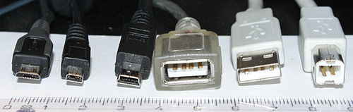
To understand the complexity of modern power delivery standards, one must first understand the limitations of the legacy systems they replaced. The “Pre-Type-C” era relied on USB Type-A and Micro-B connectors, where the original USB 2.0 specification defined a strict power budget. A standard downstream port was limited to 500 mA at 5 V, yielding a maximum power output of 2.5 W. The introduction of USB 3.0 increased this baseline to 900 mA (4.5 W), but these limits were strictly enforced by the host controller to prevent damage to USB ports.
To address the need for higher power without altering the physical connector, the USB Implementers Forum (USB-IF) introduced the Battery Charging 1.2 (BC1.2) specification in 2010. This standard allowed a portable device to distinguish between a standard data port and a high-current charger. BC1.2 defined the Dedicated Charging Port (DCP), which became the industry standard for wall chargers. By shorting the D+ and D- data pins together, a charger could signal that it was safe to draw up to 1.5 A, tripling the power of standard USB 2.0 to 7.5 W.
Operating largely outside this ecosystem, Apple developed its own charging negotiation protocols for the 30-pin and Lightning connectors. Instead of the BC1.2 method of shorting data pins, Apple chargers utilized a resistive divider network to apply specific voltages to the data lines. The connected device read these voltages to identify the charger’s capacity, with profiles ranging from 1 A (5 W) to the “Apple 2.4A” standard (12 W). This fragmentation meant that a generic USB charger designed for BC1.2 at the time might fail to fast-charge an Apple device, and vice versa.
The introduction of USB Type-C: a troubled transition (2014-2016)
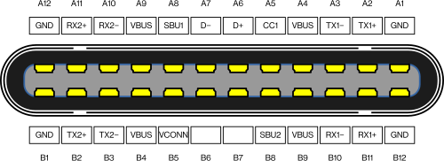
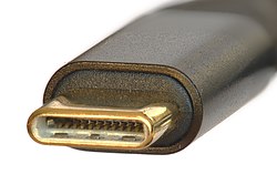
The release of the USB Type-C specification in 2014 promised to resolve historical power bottlenecks through a 24-pin reversible connector featuring dedicated Configuration Channel (CC) pins. The original specification defined several so-called “Type-C Current” modes. By using specific pull-up and pull-down resistors on the CC line, a source could advertise capability for 1.5 A or 3.0 A at 5 V. This allowed early devices to achieve 15 W charging speeds without the cost and complexity of a full PD controller.
However, this transition revealed significant safety flaws in the accessory market, specifically regarding USB-A to USB-C legacy cables. In a native Type-C connection, the source advertises its power capability; but with a legacy adapter (or even a computer USB port), the cable itself was responsible for defining the limit. Many early cable manufacturers incorrectly utilized a 10 kΩ resistor, which signaled to the device that a full 3 A was available – regardless of the actual capabilities of the source. When connected to a standard 500 mA computer port, the connected phone would attempt to draw excessive current, risking permanent damage to the host hardware. The industry eventually standardized on a 56 kΩ resistor for legacy cables, which forces the device to limit its draw to safe, legacy levels.
This period was marked by the high-profile work of Google engineer Benson Leung, who publicly tested and reviewed thousands of non-compliant, dangerous cables, highlighting the fragility of the new ecosystem. “Mr. Leung took it upon himself to purchase, test, and review a series of USB Type-C cables and accessories on Amazon, where he found a number of cables that were out-of-spec,” writes Tommy Goode. “Not only that, he found a cable that was so bad that it fried his laptop and test devices. His reviews have caused multiple manufacturers to withdraw and re-design products on sale on Amazon, and likely contributed to Amazon banning manufacturers from selling out-of-spec cables.”
Interoperability during this period was further plagued by protocol conflicts. Early USB-C phones such as the Microsoft Lumia 950 XL suffer from “boot loops” when connected to modern chargers (first-hand experience), as the device attempts to draw high operational current before the digital negotiation is finalized, triggering the charger’s safety reset. Such old devices will only properly charge from a USB-A charger – with all the potential risks of using a bad Type-A-to-Type-C cable with the wrong resistor. Conversely, handsets that strictly enforced USB-IF standards, like the original Google Pixel, would often reject proprietary chargers entirely or default to minimum speeds, creating a perception of hardware failure when the issue was actually a lack of protocol adherence.
The charging “format wars”: fragmentation and proprietary standards (2015-2019)
With mobile devices becoming more and more power-hungry and their users less and less patient, the 15 W limit of basic Type-C charging became a bottleneck. While the USB-IF was developing the Power Delivery standard, manufacturers implemented proprietary “fast charge” solutions to differentiate their products, resulting in a period of significant market fragmentation.
Qualcomm Quick Charge (QC): high voltage, low current
Qualcomm leveraged its position in the mobile processor market to establish Quick Charge (QC) as a de facto standard for Android devices. To overcome the current limitations of standard cables, QC 2.0 increased the voltage delivered to the device, pushing 9 V or 12 V to achieve up to 18 W or more. The subsequent QC 3.0 revision introduced Intelligent Negotiation for Optimum Voltage (INOV), allowing devices to request voltage in 200 mV increments to improve efficiency. However, these protocols operated by modulating voltages on the D+ and D- data lines, a method that violated the USB Type-C specification, which reserved these lines exclusively for data.
Direct charging: low voltage, high current
In contrast, Oppo and OnePlus adopted a high-current, low-voltage philosophy. Rather than stepping down high voltage inside the handset – a process that generates significant heat – these standards moved the voltage regulation circuitry to the power brick. The charger delivered a voltage close to what the battery required (typically around 4–5 V) at high currents of 4 A or more. This approach required proprietary cables with thicker copper traces and extra identification pins. Consequently, using a standard USB cable would cause the system to revert to slow, legacy charging speeds.
The alphabet soup of charging standards
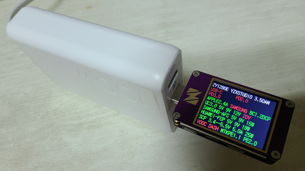
The success of these early proprietary methods triggered an explosion of copycat standards, creating a chaotic ecosystem where cables and chargers were rarely interchangeable. Consumers were faced with a bewildering array of marketing terms that could mean identical, compatible, or completely incompatible underlying technologies:
- MediaTek Pump Express: A competing protocol for devices using MediaTek chipsets, operating similarly to QC by boosting voltage.
- Huawei SuperCharge: Initially a low-voltage, high-current solution similar to VOOC (4.5 V / 5 A), but electrically incompatible with it.
- Xiaomi HyperCharge: A proprietary high-speed solution for Redmi and Black Shark devices.
- Infinix XCharge & Tecno Ultra Charge: Further variations adding to the clutter in specific regional markets.
This fragmentation meant that a “fast charger” from one brand would often trickle-charge a competitor’s device at 5 W, negating the entire purpose of the USB-C universal connector.
The illusion of choice: BBK Electronics
Perhaps the most confusing aspect of this era was the rebranding of identical technologies within the BBK Electronics umbrella (Oppo, Vivo, OnePlus, Realme). While marketed as distinct innovations, many of these standards were cross-compatible variants of the original VOOC architecture:
- VOOC (Oppo) was effectively identical to Dash Charge (OnePlus) and Dart (Realme).
- SuperVOOC (Oppo) shared its architecture with Warp Charge (OnePlus), SuperDart (Realme), and Super Flash Charge (Vivo).
While a user could technically charge a Realme phone with a OnePlus charger, the lack of explicit labeling left users guessing which “Super” or “Ultra” brick would actually work.
The offspring: UFCS – a self-proclaimed “universal” solution (2022-2025)
In a move that perfectly illustrates the industry’s tendency to solve fragmentation by creating more of it, a consortium of Chinese smartphone manufacturers including Huawei, Honor, Oppo, Vivo, and Xiaomi introduced the Universal Fast Charging Specification (UFCS) in 2022, followed by the second version, UFCS 2.0, announced in May 2025.
Ostensibly designed to unite the fragmented Chinese fast-charging market under a single protocol, UFCS entered a world already struggling to choose between USB PD, PPS, and legacy proprietary methods. The result recalls the classic engineering paradox:
While UFCS promised cross-brand compatibility, it arrived years after USB Power Delivery had effectively won the war, adding yet another layer of complexity to the history of charging fragmentation. The latest revision, UFCS 2.0, explicitly acknowledges that the format war is far from over. While the protocol standardizes the interface and negotiation handshake to ensure cross-brand compatibility, it limits the universal charging rate below the theoretical maximums of brand-specific hardware. This at least allows consumers to use charging accessories of different brands interchangeably – while still reserving peak charging speeds for manufacturer-specific, proprietary implementations.
The multi-standard charger crisis
The proliferation of proprietary charging protocols created a severe compliance crisis within the ecosystem. The USB-IF explicitly stated that for a device to be USB-C certified, USB Power Delivery must be the only method used to modulate voltage beyond 5 V. Consequently, proprietary methods like QC 3.0 and VOOC were effectively “illegal” under strict USB-C compliance standards. These protocols violated the specification by monopolizing the D+ and D- data pins for power negotiation – potentially interfering with data transmission – and by introducing voltages such as 9 V or 12 V onto the VBUS without the standardized Configuration Channel (CC) safety handshake, posing electrical risks to non-compliant devices.
The market responded to this fragmentation with “universal” chargers. These devices often utilized a single charging IC shared across multiple ports, claiming support for PD, QC, and numerous other standards simultaneously. However, the engineering compromises required to support these incompatible protocols created a new set of reliability issues that persist in the market today.
Negotiation loops and protocol conflicts
Chargers designed to “intelligently” auto-detect whether a device requires legacy Quick Charge or modern Power Delivery often enter infinite negotiation loops due to protocol conflicts.
- Connection: A device connects to the charger.
- Detection: The charger simultaneously listens for legacy QC pulses on the D+/D- lines and digital PD packets on the CC line.
- Conflict: Certain devices (notably specific Xiaomi or Samsung models) may pulse QC signals while simultaneously initiating a PD handshake.
- Failure: The charger’s controller receives conflicting instructions and triggers a safety reset.
This cycle repeats indefinitely, manifesting to the user as a device that begins charging, stops, and restarts every few seconds without ever establishing a stable connection. Notably, similar symptoms plagued early iPad Pro models when using USB-C to Lightning fast charging; while the underlying cause differed, the user experience of endless disconnection loops was identical.
The “reset” phenomenon in multi-port chargers
A frequent issue with modern GaN (Gallium Nitride) multi-port chargers – unrelated to the “alphabet soup” of charging protocols – is the tendency for a connected device to disconnect and immediately reconnect when a second device is plugged in. This “reset” is not a manufacturing defect but a consequence of rigid power negotiation rules and cost-saving circuit design.
- Scenario: A 65 W charger has two ports. Device A is charging at 60 W on Port 1.
- Event: Device B connects to Port 2. The charger must split the total 65 W budget (e.g., reallocating to 45 W and 20 W).
- Mechanism: Most charger controllers lack an implementation of Dynamic Power Management. The standard engineering solution is to cut power to all ports (Hard Reset), re-read the resistor values, and re-advertise new Source Capabilities (PDOs) that reflect the new power split.
- Consequence: Devices with internal batteries, such as smartphones, simply resume charging after the interruption. However, devices without batteries – such as USB-C powered routers, single-board computers, or hubs – suffer a hard power cut and reboot, potentially resulting in data loss.
The USB Power Delivery specification explicitly defines mechanisms for a source to update its capabilities dynamically without interrupting the voltage bus (VBUS). By forcing a hard reset to re-distribute power, these shared-IC chargers fail to utilize the required protocols for seamless operation, effectively violating the standards mandated for USB-IF certification.
The “C-to-C” failure: when USB-C is not really USB-C
A frequent frustration with budget electronics – such as portable fans, flashlights, and toys found on cross-border marketplaces – is that they often refuse to charge when connected to a modern USB-C charger. Users find that these devices, despite having a physical USB-C port, remain dead when using a C-to-C cable, yet charge perfectly when using an older USB-A to USB-C cable.
The issue stems from cost-cutting during manufacturing. For a USB-C port to function correctly, the device must contain specific internal components that signal its presence to the power source. Many low-cost manufacturers simply omit these components to save pennies per unit. This omission breaks compatibility because modern USB-C chargers operate as “Cold Sockets.” To ensure safety and prevent damage to exposed pins, they keep the VBUS voltage at 0 V by default. The charger “listens” for a signal from the device before releasing any electricity. If the device lacks the hardware to send that signal, the charger assumes the port is empty and refuses to send power.
In contrast, legacy USB-A ports are “Hot Sockets.” They output 5 V unconditionally, without asking for permission. A USB-A to USB-C cable mechanically bridges this always-on power to the device, allowing it to charge despite its non-compliant engineering. The device isn’t actually negotiating power; it is simply relying on the fact that the older charger is too “dumb” to perform the safety checks that the newer charger enforces.
The open standard: PD 2.0 and 3.0
The industry eventually converged on USB Power Delivery (PD) as the singular, unified standard, driven by the USB-IF’s iterative improvements to match and eventually supersede the features of proprietary competitors. This process began with USB PD 2.0, which marked an architectural shift from analog signaling to purely digital communication.
Unlike previous methods that relied on measuring resistance or voltage levels on data pins, PD 2.0 utilizes the Configuration Channel (CC) to transmit data packets using Biphase Mark Coding (BMC). This digital handshake allows the power source (charger) and sink (device) to exchange detailed information about their capabilities. PD 2.0 standardized power levels into fixed voltage rails of 5 V, 9 V, 15 V, and 20 V. The specification defined a maximum power delivery of 100 W, achieved by driving 20 V at 5 A. To ensure safety at these higher currents, the standard mandated the use of electronically marked (E-Marker) cables. These cables contain a chip that digitally certifies the cable’s ability to handle the thermal loads associated with currents exceeding 3 A, preventing high-power sources from overheating inferior cabling.
While PD 2.0 offered high power, its rigid fixed-voltage profiles lacked the granularity required for the most efficient modern charging. Converting 9 V from a charger down to the ~3.8 V required by a lithium-ion battery generates significant heat inside the mobile device. To address this, the USB-IF released USB PD 3.0 with Programmable Power Supply (PPS).
PPS was a critical evolution that effectively neutralized the technical advantages of proprietary direct-charging standards like VOOC. Instead of forcing the device to accept fixed voltages, PPS allows the sink to request specific voltages in precise 20 mV increments and adjust current in 50 mA steps. This granularity enables the smartphone to request the exact voltage required by its battery at any given moment, bypassing inefficient internal voltage conversion and significantly reducing thermal buildup. Major manufacturers diverged in their adoption of this technology; Samsung heavily integrated PPS for its “Super Fast Charging” branding to manage heat, while Apple largely adhered to the fixed voltage profiles of PD 2.0 for the iPhone until later generations. By incorporating these thermal management capabilities directly into the open standard, PD 3.0 rendered the fragmented landscape of proprietary charging technically redundant for compliant devices.
Breaking the 100W barrier: PD 3.1 and Extended Power Range (EPR)
As the USB-C interface began to replace proprietary barrel connectors on high-performance laptops, the 100 W limit defined by the previous standard became a significant constraint. While sufficient for ultrabooks and business machines, mobile workstations and gaming laptops frequently require power envelopes ranging from 140 W to 240 W to operate under load without draining the battery.
To address this, the USB-IF released USB PD 3.1 in 2021, introducing Extended Power Range (EPR). This specification raised the theoretical maximum power delivery from 100 W to 240 W. The engineers chose not to increase the electrical current beyond 5 A. Pushing the current higher would have required significantly thicker copper conductors, resulting in cables that were stiff, heavy, and physically impractical for consumer use. Instead, EPR achieves higher wattage solely by increasing the bus voltage. In addition to the standard 20 V ceiling of the Standard Power Range (SPR), EPR introduces three new fixed voltage levels: 28 V, 36 V, and 48 V.
Operating at voltages as high as 48 V introduces new safety challenges, particularly the risk of electrical arcing during connector detachment. Consequently, PD 3.1 mandates strict safety protocols involving updated cable identification. Standard 60 W or 100 W cables are electrically incompatible with EPR voltages. To access power levels above 100 W, the system requires specific EPR-rated cables containing updated E-Marker chips that signal support for up to 50 V. The power source performs a mandatory check for this specific EPR bit in the cable’s identity message. If the handshake fails or the cable identity is ambiguous, the charger physically restricts its output to a maximum of 20 V, ensuring that legacy cables are never exposed to dangerous voltages.
The unification period (2024-2026)
The period between 2024 and 2026 marks the refinement and unification phase of USB-C. This era is defined by the harmonization of charging protocols and the integration of smarter thermal management into the standard.
USB PD 3.2 and the unification of AVS
Before 2024, high-power charging (EPR) and standard charging (SPR) used different methods to adjust voltage, creating unnecessary complexity for engineers. USB PD 3.2 resolved this by introducing SPR AVS (Standard Power Range Adjustable Voltage Supply). This update mandates that chargers supporting adjustable voltage must now use the AVS protocol across the board. Unlike the older PPS standard, which could be sensitive to cable quality, AVS offers a more robust control loop. This simplification allows a single control algorithm to manage the entire power spectrum – from 5 V up to 48 V – ensuring greater stability and efficiency for modern devices.
Apple’s shift to Dynamic Power
With the iPhone 17 generation, Apple aggressively adopted these modern standards. Rather than relying on fixed voltage profiles, Apple implemented a “Dynamic Power” profile based on the new SPR AVS protocol. This technology allows the iPhone to request precise voltage adjustments to sustain charging speeds of 40 W, with peaks up to 60 W. By fine-tuning the voltage input, the phone forces the power brick to handle the heavy lifting of voltage regulation. This keeps the handset significantly cooler during fast charging, allowing it to sustain top speeds for longer periods than was possible with older fixed-voltage chargers.
Qualcomm Quick Charge 5+
Qualcomm has also evolved, moving away from the proprietary “format wars” of the past. Quick Charge 5+ is now a software layer built directly on top of the standard USB PD 3.1 protocol. The key feature of QC 5+ is thermal telemetry: the phone communicates its exact battery temperature to the charger in real-time. The charger then micro-adjusts the voltage to keep the device in its optimal thermal zone. Crucially, because it is built on the open standard, a QC 5+ phone remains fully compatible with any generic USB PD charger, offering a “best of both worlds” solution for consumers.
Regulatory forces: the EU Common Charger Directive (2024-2026)
The most significant driver of recent standardization is European Union Directive 2022/2380. By replacing voluntary compliance with legal mandates, the EU has set strict deadlines that have already begun affecting the global hardware market.
Phase 1: small electronics (December 2024)
As of December 28, 2024, the first phase is in full effect. All mobile phones, tablets, cameras, headphones, and handheld consoles sold in the EU must feature a USB Type-C receptacle.
Beyond the physical connector, the directive addresses charging protocols. It stipulates that any device capable of charging faster than 15 W must support USB Power Delivery (PD). This effectively eliminates proprietary lock-in and aims to put an end to the “format wars”. While manufacturers can retain proprietary modes for peak speeds (hello, UFCS 2.0!), they must provide a functional USB PD fallback mode. This ensures that a device will charge at a respectable speed when connected to any standard PD charger and guarantees basic interoperability.
Phase 2: the laptop mandate (April 2026)
The second phase arrives on April 28, 2026, extending the mandate to laptops. This deadline signals the end of proprietary barrel plugs for the majority of portable computers. Manufacturers are legally required to transition all notebooks capable of operating with up to 100 W of power to USB-C charging.
This shift commoditizes the laptop power supply. It eliminates the incompatibility of chargers between different computer manufacturers, allowing users to utilize a single standard brick for almost any laptop model and significantly reducing electronic waste.
The high-performance amendment
To accommodate hardware with higher energy demands, the directive incorporates the 240 W capability of the USB PD 3.1 Extended Power Range (EPR) standard. This amendment ensures that gaming laptops and mobile workstations are included in the mandate. By late 2026, the vast majority of portable computers – excluding only the most extreme power users – will be unified under the USB-C EPR standard.
Conclusion
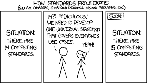
The journey of USB power delivery has been a decade-long struggle between the ideal of a universal standard and the reality of “14 competing standards becoming 15” (thanks, Randall!). The early years (2014-2016) were marred by hardware incompatibilities and interoperability disasters, from melting cables to infinite boot loops. The subsequent era was defined by a “format war,” where consumers were forced to choose among incompatible fast-charging labels, effectively negating the physical universality of the Type-C connector.
However, the 2024-2026 era marks the definitive maturity of this ecosystem. With the technical capabilities of USB PD 3.1 EPR and PD 3.2 SPR AVS resolving the power and thermal challenges of high-performance hardware, and the EU Common Charger Directive providing the necessary regulatory enforcement, the industry has effectively converged. The vision of a single charger capable of powering a smartphone, a high-end laptop, and accessories regardless of brand is no longer a theoretical goal but a technical reality and a legal requirement. While legacy devices will persist, the future of power delivery is unequivocally standardized, intelligent, and universal.
A good power source is crucial for investigations dealing with external storage media. Insufficient power may cause speed drops, intermittent disconnections, read errors, and other issues; see Effective Disk Imaging: Ports, Hubs, and Power for more details.
Reference: brief comparison of major charging standards and capabilities
| Standard | Max Voltage | Max Current | Max Power | Voltage Adjustment | Negotiation Protocol | Status (2025) |
|---|---|---|---|---|---|---|
| USB 2.0 / 3.0 | 5 V | 0.5 – 0.9 A | 4.5 W | None | Host Enumeration | Legacy / Fallback |
| BC 1.2 (DCP) | 5 V | 1.5 A | 7.5 W | None | Analog (D+/D- Short) | Legacy / Fallback |
| Type-C Current | 5 V | 3.0 A | 15 W | None | Analog (CC Resistors) | Basic Type-C Baseline |
| QC 2.0 / 3.0 | 20 V | ~3 A | 18 W+ | 200 mV Steps (QC3) | Analog (D+/D- Pulse) | Deprecated (non-compliant) |
| VOOC / Dash | ~5 V | 4 A – 10 A | 20 W – 100 W | N/A (Direct) | Proprietary (D+/D- or Pin) | Integrating into PD |
| USB PD 3.0 (PPS) | 20 V | 5 A | 100 W | 20 mV Steps | Digital (CC Line BMC) | Mainstream Standard |
| USB PD 3.1 (EPR) | 48 V | 5 A | 240 W | Fixed + EPR AVS | Digital (CC Line BMC) | High-End Standard |
| USB PD 3.2 (SPR AVS) | 20 V | 5 A | 100 W | SPR AVS (100 mV) | Digital (CC Line BMC) | Modern Standard (2024+) |
For more information, check out these articles:
- The bewildering world of USB-C charging, explained | PCWorld
- USB-PD Power, Quick Charge (QC) Apple & GaN Devices | CodeX
如有侵权请联系:admin#unsafe.sh